Wooden Big Wheels Tricycle: Part 4 ~ Finalizing the Design
We are now in the home stretch of finalizing this massive Wooden Big Wheels Tricycle on CNCKing.com!
I’ve now modified the seat so it fits perfectly within the new parameters I’ve established and got rid of the raised sides so that even larger people can easily sit in it. Now I need to get the steering column resolved.
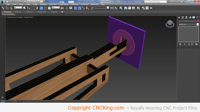
After a lot of thought, I’ve come to the conclusion that the easiest way to build the steering column into the frame is to use a two stage process similar to what I used for the back wheels. Basically, you have one round disk that turns inside of another part with a round hole in it. This will make sure that there is just enough movement to allow the swivel to be easy yet strong enough not to break from the forces involved. The part you see in the picture will slide down the shaft.
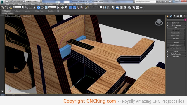
I never built a vehilcle that I could ride with a CNC machine much less a steering column but this picture looks fine except it isn’t possible to assemble. These happen regularly and I generally catch all of them. Basically the steering column would slide into place with plates keeping it in place. It can’t be pushed up because the steering arms block it in place but can slide down so I thought of just putting guides through the column on the other side but if you look carefully, how can I possibly slide these blocks in place if I have a solid frame on both sides? It simply isn’t possible so my initial idea doesn’t work. They can rotate fine but I just can’t slide them through the frame. The solution is either make holes in the frame to allow this (weaking the structure in the process) or thinking of another way to stick locks in place. After half an hour of trying to think of an easy way around this, I realized that the steering column can swivel 90 degrees at which point, sliding the blocks in place woudln’t pose a problem at all! Sometimes I overthink even the simplest of issues!
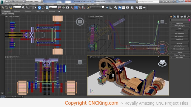
I moved the entire arm up 30 degrees after a few additional modifications to the frame and after doing a final review of every part, I’ll call this model finished. I was thinking of adding a basket in the back but it’s not really needed as the storage in the front is pretty large to hold a wallet and anything else you may have in your pockets.
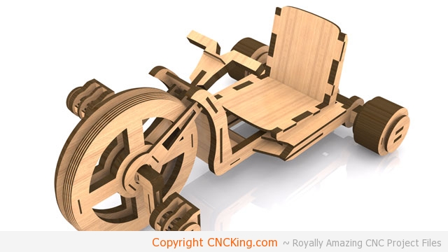
This model is roughly a meter and a half long, a meter wide and half a meter high and is made-up of 237 pieces. My wood is 6.7 mm instead of 6 mm as this model is designed for so I’ll scale everything up to fit accordingly except I have one issue, the largest wheel in this model would come to 61 cm from 55 cm from this upscaling which is just the limit of my ShopBot Desktop which may pose some problems but the next sized wheel comes to 58 cm which is fine so if I have any issue, I’ll just double-up the next size up instead of trying to cut the larger one to right size.
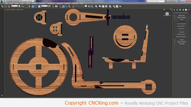
Having everything component based will make sorting the cutting files easier and more inportantly, allow me to make more sense of all these pieces.
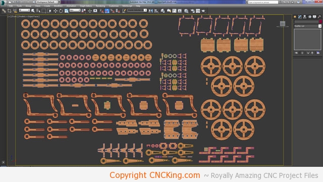
I then broke the components down into their individual pieces to all be facing me, as you can visually see, the back wheel is by far the most complex part of this project with about a third of the total piece count.
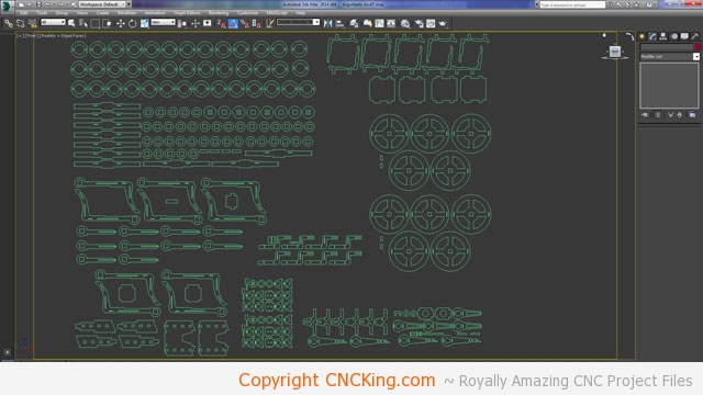
After getting rid of the extrusions on all these parts, I convert these 3D parts into 2D outlines which can then be used for toolpathing.
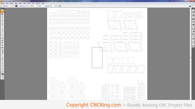
The square in the middle of the page represents my board size of 600 x 1200 mm. As you can see, I’ll be using quite a few of them and I need to optimize all my parts to fit onto this board. Just looking at the wheels it seems I have a full sheet there alone (4 x 600 x 1200 mm).
