Sydney Harbour Bridge: CNC Laser to Router Conversion 7 ~ PartWorks Dogbones
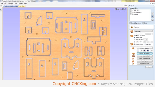
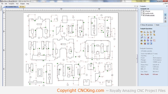
The preview of the cutting looks good but there is one major problem – I’ll be cutting out the drill holes first, followed by the inside parts but what about the outside parts? How will they stay on the board and not fly all over the place? I need to add tabs to all of the Sydney Harbour Bridge parts.
I hope you are enjoying this design process as I’ll be doing a lot more of it here on CNCKing.com!
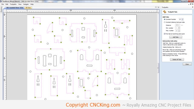
I could automatically add tabs to save time but I prefer to place my along edges, sometimes an automatic tab is at the wrong spot and makes it hard to get the piece out of the board. I find putting tabs on corners the easiest to remove or along straight lines but not on inside corners as the extra material can affect how pieces interlock.
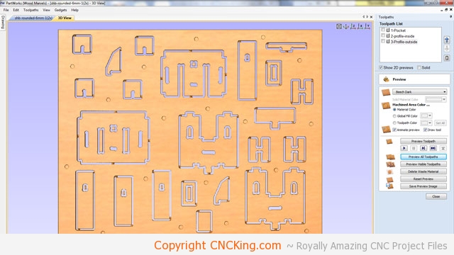
Everything now looks perfect except for the small windows. I’ve decided to leave them out in this case as somebody could still cut them out using a smaller bit after they buy my files but my focus here is to test the Sydney Harbour Bridge model, these small details don’t affect my build process nor the resultant model for sales. I could make them wider of course but again, not a big deal to me as they will show-up in the 3D assembly animation I make and I doubt most people will even notice them missing.
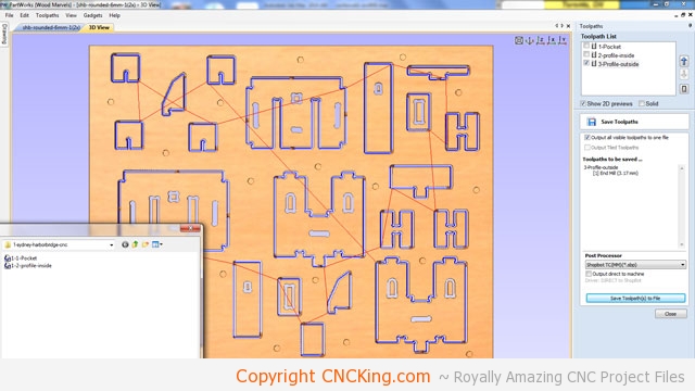
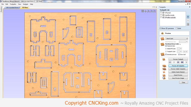
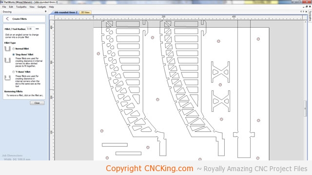
Now I save the individual Sydney Harbour Bridge toolpaths, you can see the path the table router will take and the outlines of the parts that will be done in that process (in this case, outside tool paths).
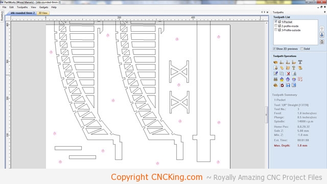
As previously mentioned, I need to make two tower sections (one at each end of the bridge spans) but if I cut the same board 2x, my screw holes will be in exactly the same place which means that my hold down will be less than optimal. I could move screw holes individually to new places on the board but that takes too much time – a quick workaround to this is to simply rotate the entire drawing 180 degrees, this way the parts are in a new location and screw holes are also in a unique locations for optimal support and hold down.
I had to recalculate the Sydney Harbour Bridge pieces tool paths but using this “spin 180 degrees” method, the process was very simple, all the tabs are in the same place and in less than a minute a whole new board was created that is strong, well supported and won’t move around.
I’ve never done this before but it seems straight forward to have the board cut dead center in the bridge span. What I’ll have to do is cut the board then move it down (it’s one long piece), re-set the home position to be 0 on the Y axis exactly where the board cutting was stopped (dead center in the middle of the span) and then cut the second half of the board. This is a theory at least so we’ll find-out if it works!
There are two challenges here, the first is making sure I’m dead-on as per the Y axis but also on the X axis… if the board moves only 2-3mm to the left or right (X axis) then my spans will not be symmetrical as one half will be taller or shorter than the other. I’ve been racking my mind as to how to lesson the error on this happening and I’ve come to the conclusion that the only way to do so is to re-set the home position on my ShopBot Desktop between these cuts and make a long, perfectly straight board that the entire length of the board can rest on that I double-check with my table router to be dead straight on the Y axis (top and bottom X axis are the same position).
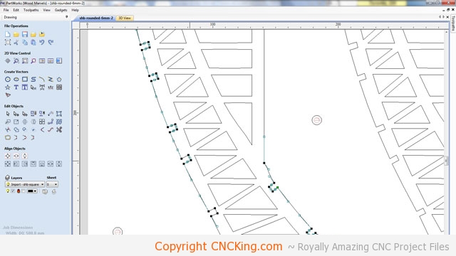
This will take a while but there isn’t any fast way to remove the brezier splines and replacing them with dog bones. Like I did for the towers on both sides of the spans, within PartWorks, I select the node editing tool and hover over the area I want to modify, when a squiggly line appears, I press “l” on my keyboard to make it a straight line.
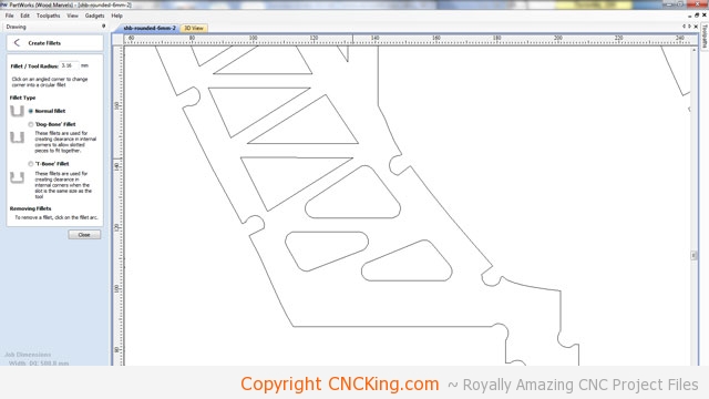
Although I don’t need to make the inside sharp corners in the Sydney Harbour Bridge spans rounded as the router will do this by default, I’m going through the process of optimizing it simply to provide a more accurate render and associated 3D animation for this project. I’ve made a lot of models and showing sharp inner corners when you design a project for a CNC table router isn’t a proper portrayal of what the consumer is buying although my old way of thinking was to leave them sharp as I use a 1/8th straight double-flute bit while somebody else would use a 1/64th straight double flute bit so the she differences would be far less apparent. I do provide the straight files as well as the rounded ones so if somebody wants to use a different bit or scale, they can easily adjust the drawing to suit their CNC’s capabilities.
On the left is the CNC table router version of this Sydney Harbor Bridge CNC model while on the right would be the CNC laser cutter version, it’s a great comparison between the capabilities of each technology. Notice the dog bones on the bottom segments that will go into the towers and the rounded inner holes within the bridge span itself.