Sydney Harbour Bridge: CNC Laser to Router Conversion 6 ~ 2D Exporting to PartWorks
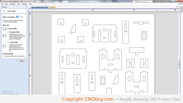
Partworks, which came with my ShopBot Desktop that I’ve made lots of videos with here on CNCKing.com, is a great program for getting the Sydney Harbour Bridge model files ready for CNC table routing. Unlike a laser, the table router needs to know what parts are inside and outside and the movements and sequence of cuts must be outlined ahead of time as the physical contact of the spinning bit will affect the output quality you produce.
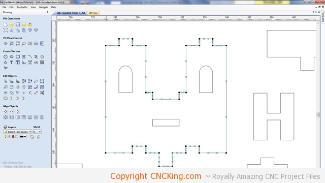
You’ll notice some pieces don’t have a dogbone, the reason for this is that sometimes my vectors aren’t closed properly from their originals within Autodesk’s 3DS Max. This happens every once in a while and isn’t a big deal as even if I have a square inside corner to these pieces, the bit will make it rounded by default anyhow. Sometimes though, you end-up with a piece looking like the above picture – it prevents you from adding dog bones which means if you cut the piece as/is, it will have rounded inner corners which don’t work very well for interlocking parts as it prevents the piece from going all the way down onto the bottom of a part. The solution in this case is to select a node from the left menu and hover over the line, once you see a small squiggly line, you press “l” on your keyboard and it fixes the issues.
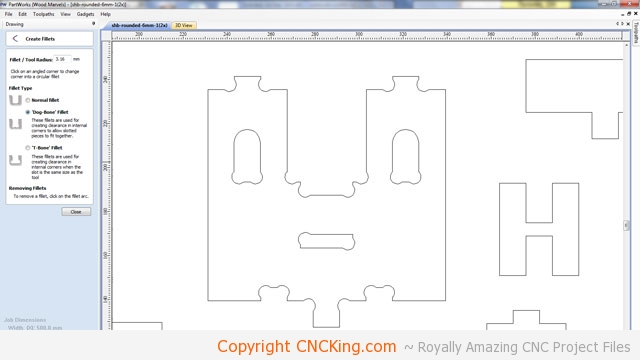
As you can see, the result in this case was a piece that looks like it has been chewed-up to look like dog bones – hence the name. I really should have made this Sydney Harbour Bridge model even bigger but in this case, it’s the first time I index a project and wanted it to go in halves and not thirds – as there is a smaller likelyhood of something going wrong in my measurements. Regardless, the model still looks great and these parts will still be plenty strong. The great part about having your own CNC table router and lots of material is that you can always go back and scale a drawing up further to make it bigger using this workflow. I’d just change the grids to “2” instead of “4” I used in this project and go through all the steps again.
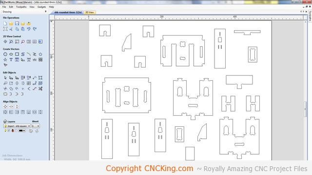
This model is now optimized to be cut – I need to duplicate this board twice (one for each side of the Sydney Harbour Bridge). There are a few pieces that are of concern, such as the “H” shape as the material is thin so what I’ll do add a few more to the board in case they are cut. Also, the little windows in the towers might be too small. I did forget to optimize a few shapes – do you see them?

The next step after the Sydney Harbour Bridge model pieces are optimized is adding screw holes – this prevents my CNC table router from going over screws (if I put them randomly on the board) as there is no way to see the paths on an empty board. Add more screws than not enough.
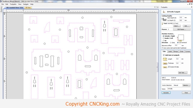
Partworks is a great program and it allows me to do a “virtual CNC table router test” which will help me isolate further issues but before we do that, we need to create tool paths to tell the router which parts are inside, outside and which are pockets. We can also define the order and position of the initial plunges but the default settings are so good for my application, I don’t worry about it. What I did here was select the outside parts and chose a bit so the ShopBot will know this critical information to generate the G-Code from for the Sydney Harbour Bridge model.
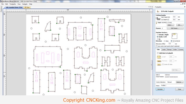
I’ve now selected the inside toolpaths, as you can see, the calculations for the outside toolpaths is already done (you can see the arrows going along the outside edges of all the shapes). Here I filled information to tell the ShopBot Desktop to cut on the inside (as opposed to the outside) of the pieces.
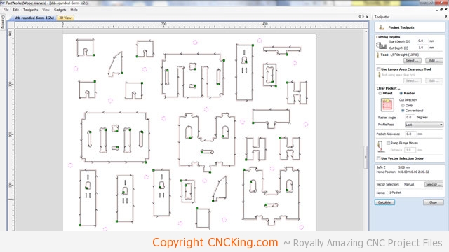
Now that the inside and outside parts are figured-out by the software, I’m left defining the screw holes – I don’t want these to go all the way through, only 1mm into the board and I’ll see the position (my board is 6mm remember). Again, the purpose of screw holes is to define where I put the screw and nothing else… I don’t want to weaken the board by going too deep.