Sydney Harbour Bridge: CNC Laser to Router Conversion 3 ~ Taking Shape
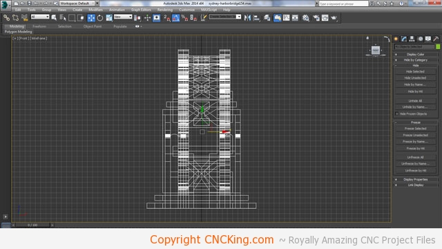
Continuing on the file conversion here on CNCKing.com… As I design all my models based on material thickness, these kind of thickness issues will reek havoc on the final design if I don’t catch all of them. Although I work in a 3D environment, it’s really 2D extruded to the material thickness. In this picture, you see a major problem. If I layer a piece over the bottom step that’s 4mm (squares help for sizing), I will have 2mm sticking out and intersecting the piece above it. Solution? Bring it down to 4mm and review the model closely to catch all of these.
The model will already be highly modified simply due to the span doubling but throw-in a 150% increase in size using the same material thickness and what may “appear” easy and straight forward has a lot of issues that could derail it in the real world. I went through TONNES of these issues with my earlier models so I know what to watch-out for but sometimes they can be hard to spot until you cut the model out and build it in the real world for the first time.
As I’ve doubled the spans, I had to make adjustments to the road that goes between them in order to have it at the right width. I also further streamlined the spans themselves to give additional tolerances for a CNC table router.

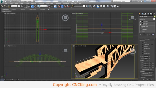
Here is one of many legacy issues I’ll have to resolve digitally before fabricating the model. As you see, there is an overlap of the squares that are used in the middle of the bridge span to hold-up the road. There are two problems here, one is the overlap but more importantly, the parts need to be made 4mm instead of 6mm as you see in the picture. This is why it’s vital that I created a grid that represented material thickness as otherwise, I wouldn’t have noticed that the issue here is really thickness related more than positional. I also need to make some slight changes to the span themselves so that the bottom matches the grid pattern I’ve established in order to avoid potential issues with both sides of the bridge.
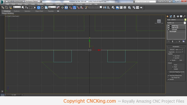
Now everything fits perfectly within my grid pattern. You’ll notice the top holes in the span don’t match it, this doesn’t matter as there are no intersecting parts to deal with but I also increased the distance between the bottom of the span and the top where the holes begin in order to give additional strength to the model. Each hole that’s made weakens the model, I want as much wood as possible on the bottom as that’s where the stress will be most shown.
Now that I have the spans and roads / sidewalks sorted out, the next step is to work on the ramps on either side of the bridge. In order to save a tremendous amount of time, I deleted one side completely which I’ll then mirror onto the other side. This means I only have to edit ONE side to get it to work perfectly instead of going back and forth one side ot the other which would only increase error.
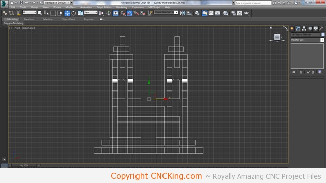
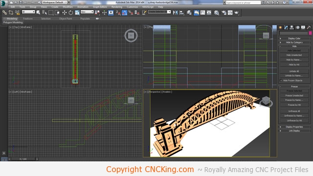
As you can see, most of the parts, after they are made 4mm instead of 6mm, fall out of my new grid format. If I didn’t have this grid established early, it would be almost impossible to get everything fitting perfectly again as, in all three dimensions, I need to modify the parts to fit back together in a tight and working order. As this is the first time I look at the model in this orientation, it also becomes clear that it’s no longer centered (see black center line)… to make my job easier from here on out, I’ll have to move the entire bridge to the new center point – the reason is simple, it’s easier to see symmetry when you have equal parts on each side.