Custom CNC Laser Downdraft Table: Design
CNCROi.com has been growing in equipment and expertise for more than the past year and as a result, some of our projects are starting to require us getting a downdraft table to limit the amount of dust that settles in the shop due to sanding and grinding.
Although I could easily buy one, it won’t be optimized with my workflow and at the same time, it showcases our capabilities regarding custom furniture (or anything else for that matter). In this case, it’s a vital piece of shop equipment that will get lots of use out of it.
We are a custom CNC shop, making our own furniture is easy compared to the other stuff we’ve done in the past for customers.
RESEARCH
As with many of the projects we do at CNCROi.com, the process starts with research to begin filling the gaps regarding what is needed and isn’t. My goal isn’t to re-invent the wheel, just make one that’s optimized for OUR production. Anybody can buy stock and then try to customize it further but it’s actually more cost-effective over the long-term to actually make something to spec.
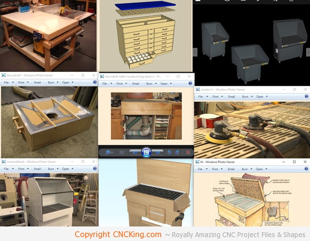
Each of these pictures have an element of interest that I wish to integrate into my downdraft table. That’s the nice thing about custom designing and building, it’s made exactly the way you want it.
PAPER SKETCHES
It’s easier to modify pencil sketches than 3D models when it comes to coming-up with concepts of what’s needed. Based on some of the pictures shown above of other downdraft tables and research I did on manufacturers of downdraft tables, I drew-up rough ideas of what I want mine to be like.
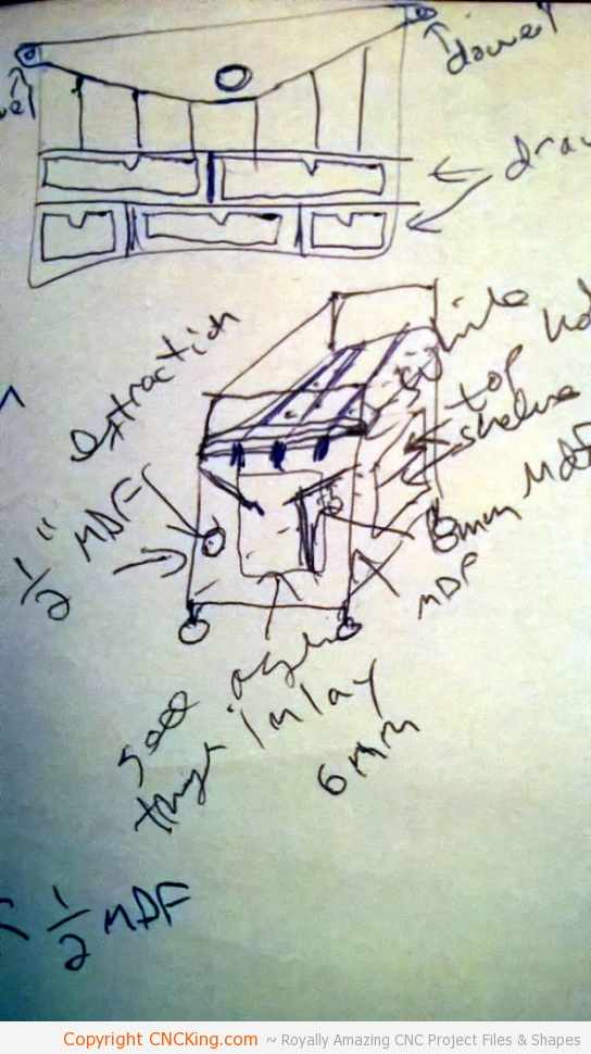
What would take HOURS to do using CAD based software can be done in seconds using pencil and pen. Once the ideas are fleshed-out, a 3D model can be done. Elements I need my downdraft table to have include locking caster wheels so it’s easy to move around the shop to where it’s needed, lots of drawers and shelves integrated into the design so all my sanding and polishing equipment and supplies are found together in the table and a vent hole out back so that when I don’t need the table, I can use the extraction machine for other purposes in the shop, rather than having it locked away in the table itself.
3D MODELING
Before starting the 3D modeling process, I need to establish limits in size and materials. I’m going to cut this entire project out using my Austrian industrial wide format Trotec Speedy 400 flexx. I can easily cut through 12 mm (1/2″) material so my initial thought was to make the whole thing out of MDF.
The problem with MDF is humidity, sure, I could seal and paint it but it’s rather heavy to work with. My second thought was to use 12 mm acrylic but that can get expensive fast but I do have a lot of scrap 6 mm (1/4″) acrylic that I could put to good use for this project. Just typical plywood is another option as, unlike MDF, it isn’t porous and built right, is plenty strong. A proper structure using even the weakest of materials is superior to using the strongest material using a bad structure.
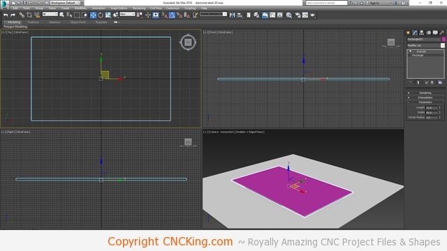
As I’m still very much debating materials, so I’m going to design this with a 15% margin on my CNC laser, meaning my maximum board size will be within 15% of the biggest thing I can put in my laser.
The problem with acrylic is static electricity and this is essentially a dust table so plywood looks like the best option and I’ve never bought plywood that was the thickness it says it was. Worse comes to worse, the plywood is undersized so I need to scale my drawing-up by 15% and I’m fine, if it’s oversized, then I just scale the table down, which is fine.
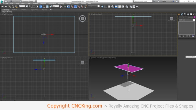
The biggest part in this downdraft table will be the surface, as such, that’s the first part I will design. I’ll use this piece to establish surface, height and width of the overall table. For this table, the height will be 85 cm tall, it will be raised-up roughly 15 cm when I add caster wheels making it roughly meter tall after initial build and if I do need to scale things-up due to material thickness not being 6 mm in thickness, I still have a table that’s comfortable to work with.
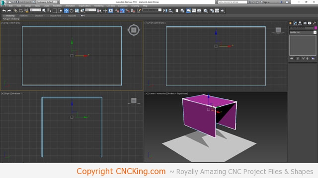
Now that I have the sizing sorted, it’s time to design roughly how this will go together. I’m seriously leaning towards a plywood build without any screws or hardware being required, as such, there will be some doubling-up involved for added strength.
Plywood face-on is rather weak but edge-on, actually pretty strong! Looks like I will have to be a bit creative, although I could technically use a meter by as long as I wish, I don’t want to use pass-through out of speed of production, so making a board a meter square isn’t going to happen.
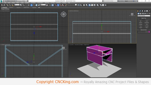
What I’m working out now is how “deep” to make the table and how I’m going to hook everything up to work properly. I don’t want the suction to be only at one end of the table as, depending on where the piece is, it will be strong on one side than another so the extraction should be centrally located in the bottom.
There will be dust build-up as well, so I want to be able to suck that out and into the filter I have in the shop rather than using an integrated furnace filter that will need periodic cleaning. As a seal is important, I’m thinking of just using duct tape along the edges on the inside as it may be the easiest method to both hold what’s there and prevent the sucking from leaking across the table.
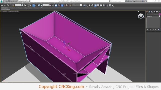
I’m now making the cone shape on the sides, again, you want the air to be sucked from above with as few dead zones as possible for dust to settle. Having slopped edges all around help with keeping suction at a maximum level throughout the downdraft process.
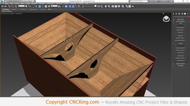
There is a lot of weight that will be added to the middle of the table where most of the sanding will be happening so I’ve built two supports that will help offset the weight downwards and keep everything from bending. If this table was made out of stainless steel, I wouldn’t need any of this, straight slats would be fine, but this will be a downdraft table made entirely of plywood and glue – no exterior hardware in any of it. These supports will also add strength to the frame of the downdraft table on the edges and lock into the bottom.
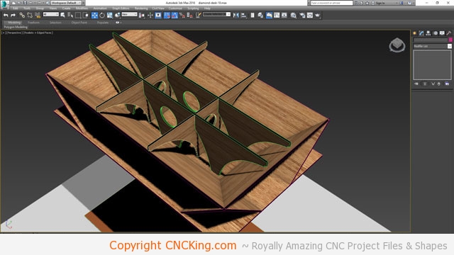
I’ve now made cross sections that will lock into the other sides and the existing cross sections I made in the previous step. I’ve now deleted my temporary sides and will begin work on the top of the table. Up to this point, everything has been positioned simply for reference purposes. Now the real designing begins on the top section of the table.
More in a few days…
